Success (or so I thought)

So I spent the majority of my day today attempting to get my radio RF transmitter and receiver for my game's location system working. After several failed attempts I thought I finally had it but now that I have reexamined what I had done I realized it is still not returning correct values. However I have learned from my mistakes and I now know how to solve it, I just need one part from Sparkfun. So until that gets here, for your learning pleasure I will document the mistakes I went through. A lot of this may sound like novice mistakes but that's because I am!
First I began by following some simple tutorials online, they wanted you to have two MCU's one for TX and one for RX but I am pretty sure i can combine it into one. I tried combining the code into one sketch. It compiled but seemed to enter an infinite loop when being uploaded. SO i decided to just focus on either TX or RX. I copied code for just TX that what increment a counter it looked like this:
/*
* Simple Transmitter Code
* This code simply counts up to 255
* over and over
* (TX out of Arduino is Digital Pin 1)
*/
byte counter;
void setup(){
//2400 baud for the 434 model
Serial.begin(2400);
counter = 0;
}
void loop(){
//send out to transmitter
Serial.print(counter);
counter++;
delay(10);
}
I checked my wiring, compiled , and uploaded, sure that this time it would work. Alas I had even bigger problems. Now my computer would completely FREEZE every time I uploaded to the MCU. Needless to say this was extremely frustrating I tried several different things but always my laptop would freeze. After scouring forums and tutorials I found the answer in the first place I should have looked in the troubleshooting page on the arduino homepage: http://www.arduino.cc/en/Guide/Troubleshooting#toc1
Silly me you can't have anything connected to the TX or RX pins, digital 0 and 1, on the Arduino board when you upload. You have to connect the TX and RX after the sketch has been uploaded.
Ok so now I was able to upload my sketch that was suppose to TX an incrementing value, RX the value and print it to the serial port. It was working but whenever I opened the serial monitor I was getting abnormal values and junk symbols. Back to the drawing board.
I added a .1 micro Farad capacitor between the ground and the Vcc of the transmitter and the receiver to prevent what they call "decoupling" in electronics, hoping that this would now make the circuit return correct values in the serial monitor. Compiled, uploaded, and still junk values.
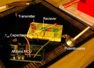
I decided to try another tutorial from Tom Igoes book "Making Things Talk" . In this tutorial you connect a potentiometer to analogIN 0 on the arduino and the transmitter to digital pin 1 TX. You than connect the receiver to RX on a USB to serial adapter and plug it into your computer. Not having a USB to serial breakout board I thought I could get away with building it all on one prototyping breadboard. That is the setup you see in the original picture.
I uploaded the code from Tom Igoes tutorial and for awhile I thought I had finally got it working. When i would turn the potentiometer the serial monitor would report appropriate values. I was very excited and was ready to post all about my success until i stopped to think....Was the device actually transmitting, receiving, and printing the potentiometer value or was it merely reading and printing the potentiometer straight off analogIN 0?? Warily I unplugged the TX pin, to my dismay the serial monitor still returned values consistent with the potentiometer, It wasn't transmitting :(. So now i know that i need to the arduino working independently of the computer off of a 9V battery with the TX on it and and USB to serial breakout-board hooked into the comp with the receiver. Anyways I learned a lot and am a lot closer to final execution.
I uploaded the code from Tom Igoes tutorial and for awhile I thought I had finally got it working. When i would turn the potentiometer the serial monitor would report appropriate values. I was very excited and was ready to post all about my success until i stopped to think....Was the device actually transmitting, receiving, and printing the potentiometer value or was it merely reading and printing the potentiometer straight off analogIN 0?? Warily I unplugged the TX pin, to my dismay the serial monitor still returned values consistent with the potentiometer, It wasn't transmitting :(. So now i know that i need to the arduino working independently of the computer off of a 9V battery with the TX on it and and USB to serial breakout-board hooked into the comp with the receiver. Anyways I learned a lot and am a lot closer to final execution.
Comments